Difference between revisions of "project07:W1"
| (One intermediate revision by one user not shown) | |||
| Line 17: | Line 17: | ||
<div style="float:left; width: 120px; height 30px; border: 1px solid #aaa; margin-right:10px;" align="center">[[project07:W5|'''W5 ''']]</div> | <div style="float:left; width: 120px; height 30px; border: 1px solid #aaa; margin-right:10px;" align="center">[[project07:W5|'''W5 ''']]</div> | ||
</div> | </div> | ||
| + | |||
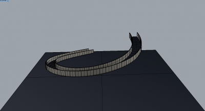
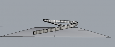
| + | In my project I tried to develop a curved walk-able 3D path. At first, it sounds as an easy assignment to achieve. I was a bit surprised that for the right orientation of the surface and the railing it proved to be a mathematical challenge that required some thinking, as there is no specific tool in grasshopper that I could use. | ||
| + | |||
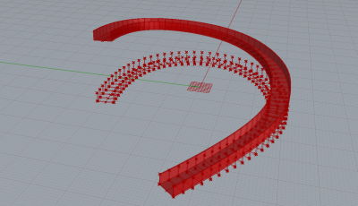
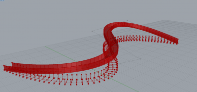
| + | At first I tried to use the command of create perpendicular frames – the result is a series of perpendicular frames to a 3D curve. Unfortunately, in this situation there is no way to orient up and down – which is essential for paths and railings. The result is more like a rollercoaster path rather than a walkable one. For this reason I rethought about how to generate it in a thorough way. | ||
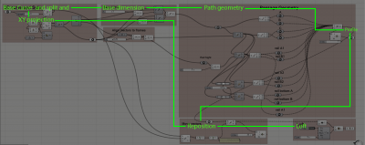
| + | Base Geometry: The path required a 3D curve. The curve splits into equal segments – and each is being assign with the railing profile – with changeable width and height. In the end – the loft and cap command makes it into a 3D object. | ||
| + | |||
| + | Orientation: In order to make the path walkable each part supposed to be horizontal to the ground plane. For that – the curve is projected into the XY plane. Afterwards, the XY curve is split and a profile is generated in each segment. This creates a horizontal path – but for a 3D curving and climbing-up path this won’t do. The next step is that every segment is moved-up into its appropriate point in the original curve. Only then the loft command is applied. | ||
| + | |||
[[File:Grasshopper_diagram.png|400px|thumb|left|Grasshopper code and Diagram]] | [[File:Grasshopper_diagram.png|400px|thumb|left|Grasshopper code and Diagram]] | ||
[[File:GD1.png|400px|thumb|left|First Path calculation]] | [[File:GD1.png|400px|thumb|left|First Path calculation]] | ||
[[File:GD2.png|400px|thumb|left|Second path calculation]] | [[File:GD2.png|400px|thumb|left|Second path calculation]] | ||
| − | [[File:GD3.png|400px|thumb|left|]] | + | [[File:GD3.png|400px|thumb|left|First path view]] |
| − | [[File:GD4.png|400px|thumb|left| | + | [[File:GD4.png|400px|thumb|left|second path view]] |
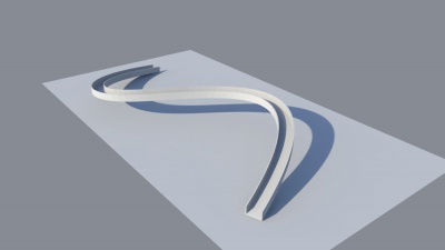
[[File:GD5.jpg|400px|thumb|left|Visualization 1]] | [[File:GD5.jpg|400px|thumb|left|Visualization 1]] | ||
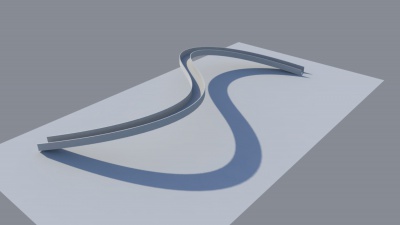
[[File:GD6.jpg|400px|thumb|left|Visualization 2]] | [[File:GD6.jpg|400px|thumb|left|Visualization 2]] | ||
Latest revision as of 13:26, 13 December 2017
Ori Gilboa
In my project I tried to develop a curved walk-able 3D path. At first, it sounds as an easy assignment to achieve. I was a bit surprised that for the right orientation of the surface and the railing it proved to be a mathematical challenge that required some thinking, as there is no specific tool in grasshopper that I could use.
At first I tried to use the command of create perpendicular frames – the result is a series of perpendicular frames to a 3D curve. Unfortunately, in this situation there is no way to orient up and down – which is essential for paths and railings. The result is more like a rollercoaster path rather than a walkable one. For this reason I rethought about how to generate it in a thorough way. Base Geometry: The path required a 3D curve. The curve splits into equal segments – and each is being assign with the railing profile – with changeable width and height. In the end – the loft and cap command makes it into a 3D object.
Orientation: In order to make the path walkable each part supposed to be horizontal to the ground plane. For that – the curve is projected into the XY plane. Afterwards, the XY curve is split and a profile is generated in each segment. This creates a horizontal path – but for a 3D curving and climbing-up path this won’t do. The next step is that every segment is moved-up into its appropriate point in the original curve. Only then the loft command is applied.
