Difference between revisions of "project03:W1"
(→Computational Flow Chart) |
(→Implementation) |
||
| Line 42: | Line 42: | ||
== Implementation == | == Implementation == | ||
| − | [[ | + | [[file: Grasshopper_Script.png|850px]] |
[Attached Grasshoppper Script] | [Attached Grasshoppper Script] | ||
Revision as of 18:54, 11 October 2016
Lars Hammer
Design Objective
The design objective of Workshop 1 is creating two line lines between which a geometry is created, relative to specific parameters. The points on the lines which will be formed between the base-curves will have to function as a base for cones. The direction of this geometry differs on the distance of one Attractor point based in the Rhinoceros environment.The size is as well relative to the distance to the attractor point. The attractor point will find a random spot within the Rhino Environment, the loop function is used for that.
Design Strategy
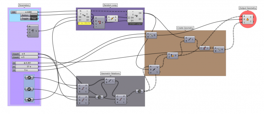
Firstly we will make two curves within the the Rhino Environment, these curves will be set to its geometry component in Rhino. An attractor point will also be specified, and set in the Rhino environment. The two curves will be divided (the division can change according to a slider) and function as a base for attachment lines between them. Then these attachment lines also get divided according to a slider. Each new point will function as a base plane for geometry and a normal which is always pointed towards to the attractor point. The length of these normals will be related to the height of the geometry. Which will never reach. The loop will be used to generate a random point within the Rhino environment. The attractor point will be looped with an random vector.
Computational Flow Chart
[Attached Illustrator File]
Implementation
[Attached Grasshoppper Script]

